User Tools
Site Tools
Sidebar
Table of Contents
Drawings management
Create phasing
Phase Manager can import drawings in different formats like DXF, SVG, or PDF.
Importing drawings
Phase Manager can import drawings in different formats like DXF, SVG or PDF.
How to import a drawing
To add a drawing click on the + button in the Drawings and phases tab of the Create phasing interface:

After graphics loading, the drawing and its nodes appears in the editor.
Drawing editor
Just after a drawing has been imported, you are redirected to the drawing editor interface.
Within the drawing editor, you can adjust the visibility of the objects that compound your drawing.
Hiding objects on the drawing
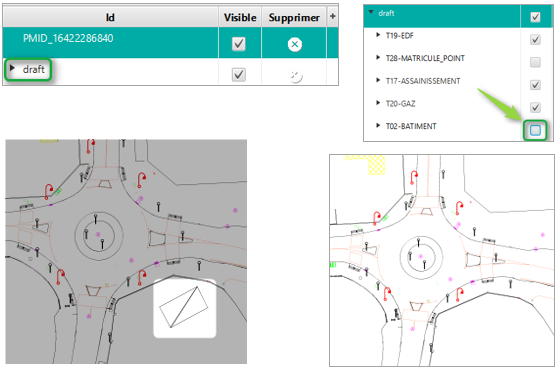
In the left panel double-click on the root object of the drawing (here « draft ») to open layers, then untick the visibility of the object you want to hide (here 'T02-BATIMENT') :
Saving a drawing
To save a drawing, click on the save check mark in the plan editor:

The map will be displayed again in the georeferencing interface which is characterized by the placement options at the bottom left:
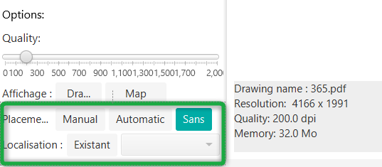
note: the georeferencing introduced with GIS in Phase Manager 4 is described here.
In this example we are not going to georeference the drawing and we click again on the save tick in the window.
Naming drawings and choosing a default one
To rename a drawing, select it then click on the rename button
How to rename a drawing

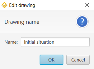
In the window that opens, modify the name of the drawing then click on OK:
Defining the default drawing
If more than one drawing is available, specify the default drawing by means of the checkbox located to the left of the drawing name:

Adding a scale and using the measurement tool
Adding a scale
It is very simple to add a scale to your drawings : click on the button  of the Drawings and phases tab, then successively on two points of your drawings whose distance between them you know.
When your drawing does not contain Metadata as it is the case with PDFs, or if it's not been georeferenced, you can fill in the scale yourself:

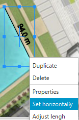
Once the scale has been validated, position it precisely horizontally by right-clicking and then Set horizontally :
You can normalize your scale to a rounded value by right-clicking and then Adjust lenght :

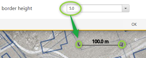
The scale is redimensioned and can now be moved wherever you want on the map. The length of the end returns of the scale is specified by right-clicking > Properties > then setting the Border height :
Using the measurement tool
Once the scale of the drawing has been defined as indicated above, orif your drawing has been georeferenced, you can use the measurement tool ![]() to display the distance between two points (below for example are the length of a building and the track width):
to display the distance between two points (below for example are the length of a building and the track width):

In this example, we realize that the scale is wrong, because the track is actually much less than 48 m wide.
It is possible at any time to redefine the scale, while keeping the existing measures.
For example, here below we modify the scale of the drawing using the known length of a building:

The other building's length and the track width measurements are automatically adjusted :


 Note : you can modify the drawing screen scale with the zoom and adjustment buttons located in the top right part of the window. Those settings are saved for each drawing.


